On all modern cars, it is common to be able to drive the car normally until the tank is completely empty. How many times have you put in enough fuel in your modern car to know that there was nearly zero left in the tank? It may have made you very nervous, but the car made it to the gas station.
It is unacceptable to the OEM’s – and to the owners – to keep at least a ½-tank of fuel in the tank in order to have good fuel delivery under all driving conditions.
Imagine driving your car and coming up to your favorite freeway cloverleaf, sweeping turn, etc. But wait, you have to tip-toe through that fun driving because the liquid level in the tank is below 1/2. Does that seem even a bit reasonable?
To solve this problem, the OEM’s have integrated many of the technologies mentioned in the earlier sections, then added a few more to make them even better. To make it easier to understand, we will call the device that integrates these features a fuel module.
In short, and what will be laid out further in this section, is that the OEM derived fuel module is simply in a different orbit than anything offered in the aftermarket. The engineering, safety, and thoughtful design of these modules makes them a game-changer for aftermarket fuel delivery, and we are fortunate to be able to take advantage of the large-scale manufacturing costs associated with them. No aftermarket company offers an integrated fuel module like those used by every OEM automotive manufacturing company on the plant. Heck, even the new Honda Gold Wing motorcycles use a fuel module design! If there were a better, less costly method for reliably pumping fuel, the brain-power at the OEM’s would have it figured out.
Please note that all modern fuel modules will not work in low-pressure carburetor applications.
Modern fuel modules perform many of the functions that were traditionally handled with separate components.
Fuel filtering, pumping, and pressure regulation can be done in the fuel module.
The fuel module also has a built-in surge tank/reservoir, venturi/jet/suction/transfer pumps to keep the reservoir full, electrical bulkheads, fuel level sensor attachment options, and excellent sealing devices.
Most fuel modules are also preloaded to the reservoir against the tank bottom using springs.
A typical modern fuel module is shown in Photo 1.
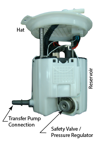
Photo 1. Note the single line output on the module hat. No return line is needed with this design (Camaro ZL1)
The fuel module shown has the following features:
- An all-in-one fuel filtering. No other filtering is needed before the fuel rail if the proper lines and line cleaning procedures are used.
- A single line output that supplies regulated pressurized fuel. No return lines or external regulators.
- A wiring plug/bulkhead connector that passes power and fuel level signals through to a sealed external plug.
- The large white cylindrical-shaped part is the reservoir. When the pump is running this reservoir is normally overflowing with fuel, hence keeping the pump constantly submerged.
- 1-3 jet pumps are used to fill the reservoir and keep the pump supplied with fresh, cool fuel.
- One of the venturi pump connections, the grey nipple on the bottom-left of the reservoir, can be used to connect remote pickups.
It’s an OEM validated design.
VaporWorx has performed extensive testing on many modules.
Single modules can support up to 960fwhp @ 60psi naturally aspirated, 800fwhp supercharged, plenty for the vast majority of builds.
They are quieter than a standard 255lph pump mounted traditionally in the tank, or in-line.
Best of all, even under very low fuel loads the module is still working due to the reservoir.
It has been shown that the module will reliably deliver fuel at very low liquid levels even when used on autocross or road courses. When the corner pickup systems are used on-track, testing has shown that liquid levels can fall to under one gallon and the module will still be effective.
Even without the corner pickups, module performance will not suffer on autocross courses with just one gallon in the tank.
Note the jet pump locations and other features on the module bottom surface in Photo 2.
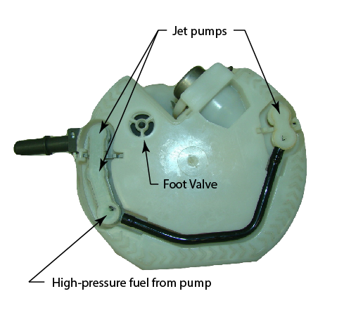
Photo 2. Bottom view of the Gen5 Camaro ZL1 fuel module. Though very similar in appearance, the LS3/L99 module does not have the black crossover tube.
An often overlooked benefit of the lower reservoir is the amount of inlet head pressure that the elevated fuel level provides.
When liquid levels in the tank are low, the inlet head (height of the fuel above the inlet) is also low. The pump, not being very good at suction, will have poorer performance vs. the same pump with more inlet head.
The lower the inlet head, the greater chance of cavitation at the pump inlet, and hence the resulting loss of fuel pressure.
This cavitation is also known as vapor lock. Unlike carburetors, vapor lock on EFI systems typically happens at the inlet to the electric pump due to high fuel temperatures and low inlet head pressure.
In order to make the fuel module shown above work in a standard mechanically regulated 4bar/58psi EFI system, the fuel pressure regulator in the module must be replaced. A VaporWorx fuel pressure regulator can be used to convert the Gen5/6 SS fuel modules to 4bar constant fuel pressure operation.
This arrangement will provide a fuel pressure vs. output curve very similar to that of a C5 FFR.
Note: Higher output fuel pumps like the Gen6/6 ZL1 and CTS-V2 fuel modules typically should have a different control strategy.
Please click here for more information (this link will skip you ahead to Part 8 of this series: “How Do PWM Returnless Fuel Systems Work?” – remember to return here to Part 6 afterwards; or you can keep reading, you’ll be there soon!)
In order to mount the fuel module into the tank, a VaporWorx fuel module mounting ring is required.
This ring, made of 304 stainless steel or 6061 aluminum, will weld on to the top of the tank.
Note that the fuel module, with its downrods and preload springs, must seat flat and be preloaded against the bottom of the tank. The fuel module is not designed to “hang in space” where the weight and side loads of the lower section are transferred through the downrods and into the bulkhead hat. If this is done the downrods will break out of the hat, leaving the entire lower section unsupported and flopping around in the tank. The fuel module must be preloaded against the bottom of the tank.
It is perfectly acceptable to have the sealing surface of the mounting rings/fuel module to be under the liquid level. It is this way in the OEM application as well.
In order to fit properly the distance from the seating surface of the mounting ring to the bottom of the tank should be between the following:
LS3 and CTS-V2 fuel modules: 5-1/2” – 7”, with 6-1/2” being ideal.
ZL1: 6-7” with 6-1/2” being ideal.
Hole diameter required for mounting ring: 6-3/8”
Cam ring diameter: 7-3/8”
Above the mounting surface of the ring a minimum of 1-1/2” is needed for module plumbing and electrical clearance. Note in Photo 3 how the module is recessed into a 1-1/2” tray for overhead clearance.
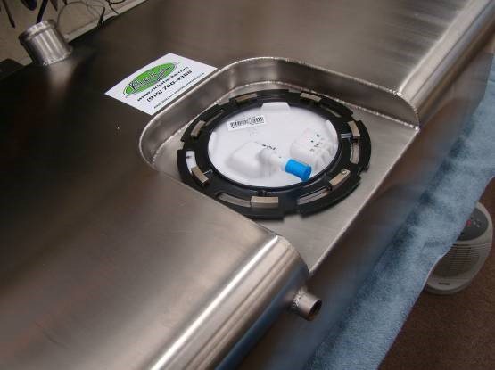
Photo 3. Note how the module is recessed so that it remains below the top surface of the tank.
Also in Photo 3 the OEM cam locking ring can be seen. The OEM o-ring seal is also used.
The outlet of the module is a GM 3/8” quick-connect and sufficient for up to 750fwhp.
VaporWorx has adapters available that will attach to the 3/8” quick connect and convert it to an AN6 male fitting.
Power wiring to the module is done using an OEM style wiring harness. A typical wiring harness can be seen in Photo 4.
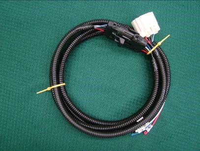
Photo 4. The white plug is the fuel module power and fuel level sensor plug.
A typical fuel line and electrical connection layout is shown in Photo 5.
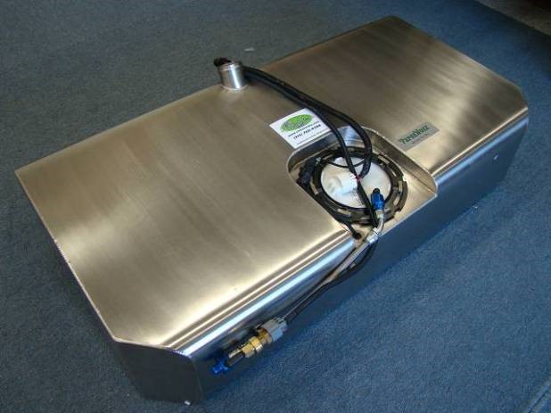
Photo 5. Note the wiring can route forward or aft but must not be pinched, cut, etc. Teflon / PTFE fuel lines are highly recommended.
The 5th-gen LS3/L99 fuel module requires a 15-amp minimum circuit.
In most cases, a relay will be needed to supply sufficient power.
It is highly recommended to use the ECM fuel pump control circuit. The ECM will automatically shut off this circuit if the engine shuts off in an accident. Most of the ECM fuel pump control circuits are BAT+ switch, meaning that the circuit connects to BAT+. The relay will need to be wired accordingly.
No additional fuel filters are needed since the final filter is built into the fuel module.
However, it is required that the fuel line from the pump to the fuel rail be thoroughly flushed before engine startup.
Using PTFE flexible and stainless hardlines will greatly reduce the chances of hose deterioration and the resulting injector clogging. Modern fuels can be very aggressive on elastomer lined hoses whereas PTFE is impervious to just about anything.
When comparing the cost of a fuel module system vs. a traditional, the costs of un-needed components should be considered.
For example, when using the VaporWorx system, the following components are no longer needed:
- External filters
- External pressure regulators
- Return lines
- Fittings, mounts, clamps, etc. to connect it all
- The room all of the above components take
- The long-term reliability of the components
Over 800 on-track and 3000+ street miles were put on the fuel module during testing.
At no time did the engine suffer due to fuel starvation except when it drained the tank dry on a road racing course.
The same module is still in use today, serving well as a test mule for the electronic fuel control systems that will be covered in the later sections.
The key to selecting the correct fuel module is to know what power level it will support.
The following guidelines can be used for gasoline engines:
Naturally Aspirated:
Under 600hp @ 60psi: Gen5 Camaro LS3 fuel module.
Under 775hp @ 60psi: Gen5 Camaro ZL1 fuel module.
Under 950hp @ 60psi: Cadillac CTS-V2 fuel module.
Supercharged:
Under 650hp @ 60psi: Gen5 Camaro ZL1 fuel module.
Under 800fwhp @ 60psi: Cadillac CTS-V2 fuel module.
Over 800fwhp @ 60psi: Twin fuel modules. (custom controller required)
For E85 applications, a minimum of 30% additional fuel capacity will be needed.
Note: The pumping section of the Gen6 ZL1 and CTS-V3 modules with the LT4 engine are the same as the Gen5 ZL1. However, the Gen5 ZL1 is usually easier to fit since it is shorter and has fewer penetrations on the hat to plug.
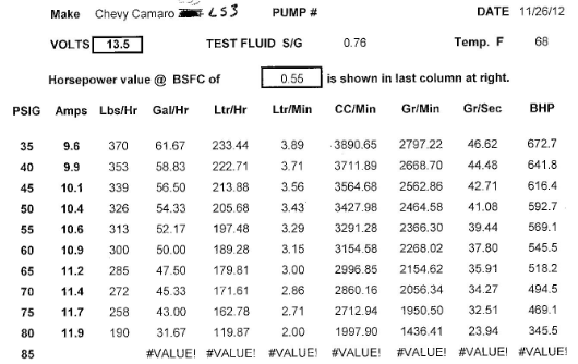
Fuel Flowrate Tables
Fuel flowrate tables for the LS3, ZL1, CTS-V2, and CTS-V3 can be found below.
Note that the BHP values are for a Brake Specific Fuel Consumption of 0.55. Adjustments according to your engine type should be made.
Camaro Gen5 LS3/L99 Fuel Module
Camaro Gen 5 ZL1, Gen6 ZL1, and Cadillac CTS-V3 Fuel Modules
(All three have the same pumping sections.)
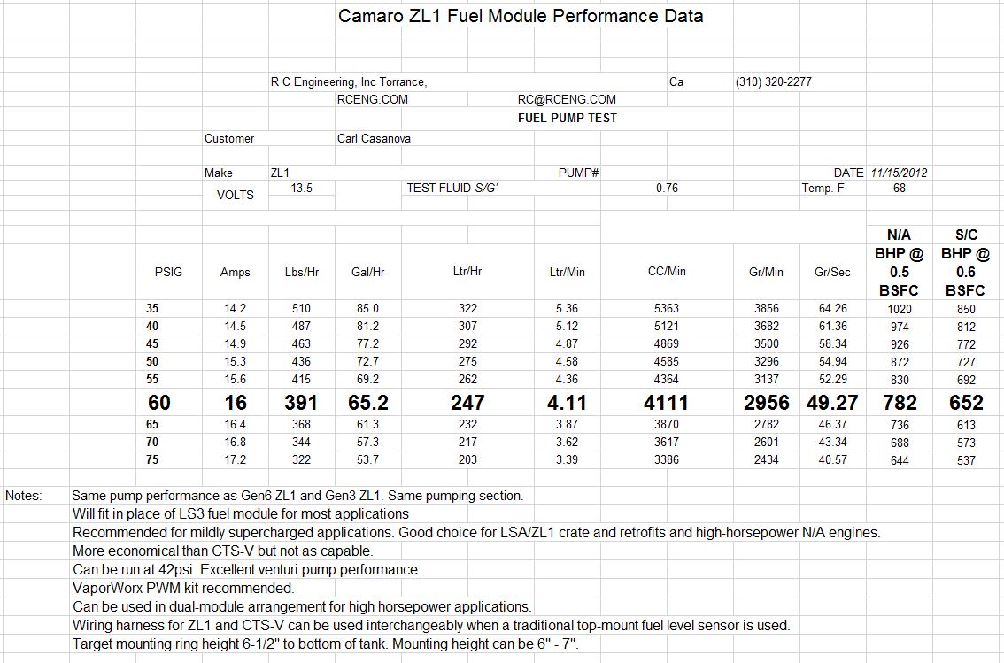
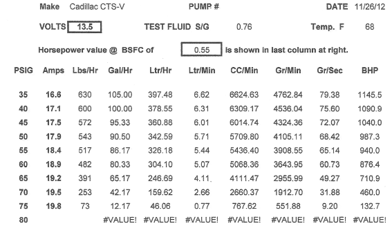
Cadillac CTS-V2 (2009-2014) Fuel Module
Key Comparisons
The overall cost of the fuel system is usually also a factor when choosing they type of system. However, all of the components of a traditional system should be weighed and compared to that of a VaporWorx PWM system.
- No external regulators, return lines, fittings, or fuel filters are needed.
- Extended pump life is expected and reliability increased.
- If big power is in the future, a larger capacity fuel module can be used now with no drawbacks, hence you avoid needing to do the job twice.
- Need even more fuel? Dual fuel modules can be used to provide 2x the amount of fuel.
Fuel module advantages:
- Excellent fuel delivery under all conditions.
- Proven OEM design and reliability.
- Readily available replacement fuel modules are as close as your GM dealer.
- OEM wiring and sealed plugs.
- OEM o-ring seals and cam rings.
Fuel module disadvantages:
- Initial costs may be higher than other systems.
- Additional fabrication typically required.
Continued Reading
This article is part 6 of the 10-part informational series: Fuel Delivery Systems – An Understanding
To continue reading in the series, use the navigation below:
Or, click here to view the full navigation/table of contents for this series.
Want to know more?
Whether you have a question about the material on this page, want to know more about our products - from purchase to installation to maintenance - or anything else, contact us anytime: we're ready to talk about your ride!