Many of today’s new vehicles have 100,000 mile warranties.
These warranties cover fuel systems as well. So, the question is how do the OEM’s get 100,000 mile reliability while still being able to have a pumping system capable of 750+ horsepower and not overheat the fuel?
Modern electronics is the answer.
In Part 7: Mechanical Systems, it was discussed how fuel was routed through the regulator and bypassed back to the fuel tank.
If the fuel pump is running at full speed, as is the case in most all aftermarket/hot rod applications, this can add a significant amount of heat to the fuel load. Most of the time, very little fuel is needed, but a pump of sufficient capacity is needed to supply the engine at wide open throttle (WOT).
Add in the heat picked up in the engine compartment by the circulating fuel, and the fuel in the tank starts to get very warm in a hurry.
It is common to find many hot rods with large fuel pumps on the side of the road with an overheated fuel pump, especially on longer road trips. The trick is to change the speed of the fuel pump so that it only pumps what the engine needs and no more. This reduces heat generation to a minimum.
The way the OEM’s control the speed of the pump is by using Pulse Width Modulation (PWM).
PWM is like turning a switch on and off very quickly.
For example, if a switch is turned on for 10ms, then off for 10ms, and the cycle repeated, the pump is working at a 50% duty cycle.
Unlike a simple voltage reduction, which leads to high amperage/heat generation, PWM creates very little heat.
Utilizing feedback from pressure sensors, the PWM controller changes the speed of the fuel pump to supply the jet/transfer pumps and engine demand, and no more. Figure 1 shows graphically the power signals that are sent to the pump.
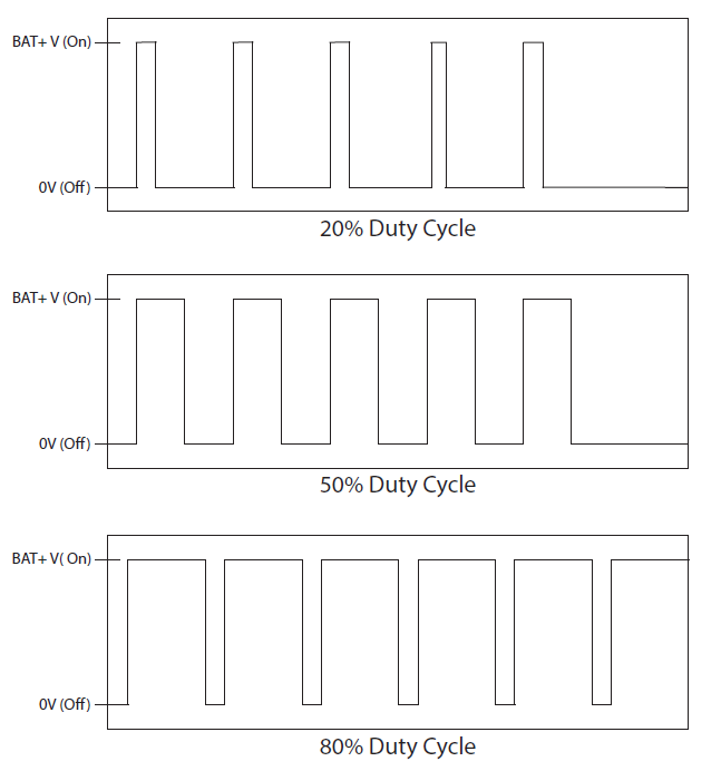
Figure 1. Typical PWM signals that the fuel pump would operate under.
There are various sensors available to provide feedback signals that can be used to change the speed of the pump.
Throttle position sensors can be used, but the fuel demand at WOT at low engine speeds is much different than WOT at higher engine speeds.
Ignition spark/RPM signals are also not reflective of what the engine fuel needs are, since downshifting/downhills can make the pump run very fast, but little fuel is needed.
All of them require a return type system since the amount of fuel pumped exceeds the needs of the engine. Hence, external regulators, return lines, and the associated hardware are required.
The most reliable method of determining the actual engine demand is fuel pressure.
The OEM’s utilize fuel pressure signal feedback and PWM to control the speed of the fuel pump.
With the combination of PWM and fuel pressure feedback, a large-volume pump that normally would produce excessive heat during low fuel demand can be slowed down.
In effect, the PWM system gives a large pump a dual personality: Slow it down for cruise and minimize heat generation, then speed it up for high fuel demand.
A pretty good estimate is that if a pump is run at 60psi in a traditional return type system vs. a returnless PMW, the power reduction at idle and cruise is 50%. If run in manifold referenced mode, 66%.
Think of it this way:
Your engine might be able to make 500hp, so why not let it run full speed all the time?
The coolant and oil would overheat, it would be just about impossible to drive, fuel mileage would be measured in gas station distances, etc.
So, put a throttle on it.
That’s what PWM is for a fuel pump, it’s a speed throttle.
In order for this system to work the normal mechanical pressure regulator must be removed.
It also means that only a single line to the fuel rail is needed.
This system simplifies and reduces the cost of the plumbing since no external filters (OEM modules only), pressure regulators, return lines, etc. are needed – just a pressure line from the fuel module to the engine fuel rail.
Figure 2 compares a full PWM returnless system vs. a traditional full return arrangement. Note the lack of external components in the PWM system vs. the return, there are no regulators, return lines, or external filters
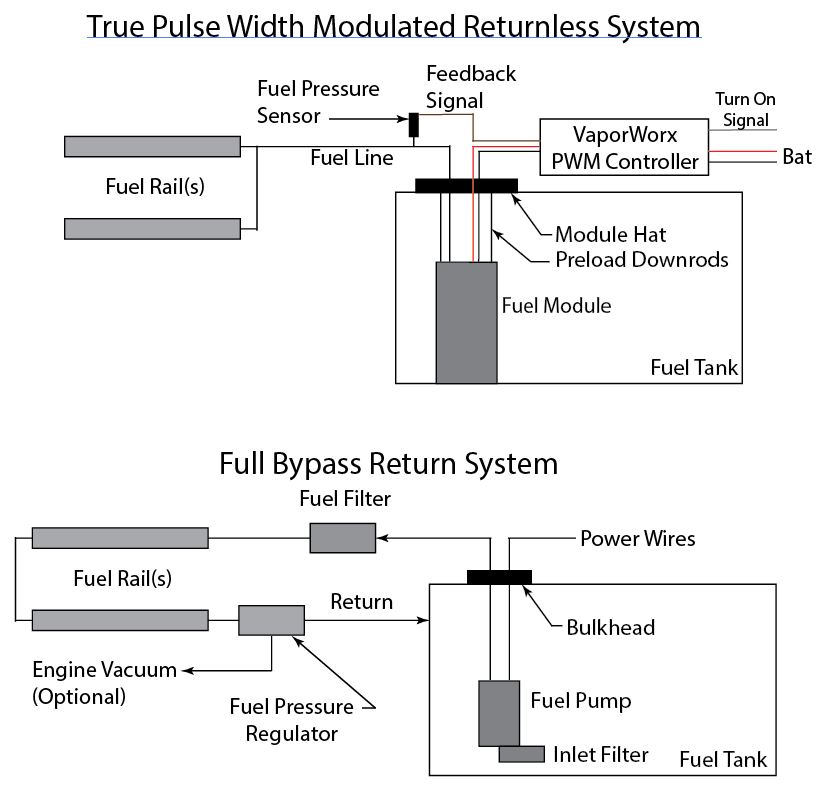 Figure 2. Note the full bypass return system does not show the fuel pump support structure, power relay, or wiring details.
Heat picked up in the engine compartment is also returned to the fuel load. Also note that the pump does not seat all the way against the floor of the tank and has poor slosh control.
There are two fuel pressure control strategies available on all VaporWorx PressureWorx PWM control systems.
The first, is a constant (static) pressure system that mimics the output of the Corvette C5 fuel filter/pressure regulator. Constant pressure between 42-60psi is typical and adjustable on the VaporWorx controller.
The other, is a manifold referenced option that provides an approximate 1:1 fuel vs. manifold pressure rising rate fuel pressure system. In other words, if the manifold pressure increases, then the fuel pressure increases the same amount.
The PressureWorx PWM Fuel Module Control System, in manifold referenced fuel pressure mode, uses the engine Manifold Absolute Pressure (MAP) sensor signal to change the output pressure of the fuel pump accordingly.
The PressureWorx system consists of the:
- PWM control module,
- GM fuel pressure sensor,
- Delphi-sealed wiring harnesses,
- and all hardware.
The PressureWorx systems will work with the 5th-generation Camaro LS3 and ZL1 fuel modules. If a higher capacity fuel pump is needed, then the Cadillac CTS-V2 module can be used.
The CTS-V2 module can supply 304lph/hr and mount in same basic envelope dimensions as the 5th-generation Camaro.
Unlike the 5th-generation Camaro LS3/L99 fuel module, running the ZL1 or CTS-V2 pump with an adapted 60psi mechanical regulator in not recommended.
First, the ZL1 and CTS-V2 required 17-19A to drive at battery voltage. That means even more heat when running at full speed all the time. It’s the equivalent of putting a 240 watt light bulb in the fuel tank.
Second, there is no regulator that will easily swap out and replace the CTS-V2 poppet valve and have an acceptable pressure curve. The 58psi regulator that does fit the CTS-V2 module will drop 13-15psi before full pump output is achieved. That is too much of a pressure drop to be effective in a high-output engine.
Both the 5th-generation Camaro and CTS-V2 fuel modules have a safety/poppet valve installed that looks like a traditional fuel pressure regulator.
In the 5th-generation LS3/L99 module this poppet valve is replaced with a 4th-generation Camaro fuel pressure regulator when the module is used when running at full battery voltage and a 58psi output. The removed OEM poppet valve has an 88psi bypass pressure, far too high for engine needs.
However, this high bypass pressure is needed in the PWM systems so that the fuel pressure sensor can work without the chance of the mechanical regulator/bypass coming into play.
What the poppet valve does is help relieve fuel pressure once the ignition key is turned off, or in case of controller failure.
When the ignition is turned off, the fuel injectors immediately shut and the power to the pump is turned off. However, the pump is still spinning due to inertia, hence the fuel pressure will spike. The safety valve bleeds off excessive fuel pressure.
With the PressureWorx PWM systems, the safety valve is not replaced. The module is used as it would be as delivered from GM.
A typical complete VaporWorx PWM system is shown in Photo 1 below. This kit contains everything needed to drive the fuel module electrically. GM fuel pressure sensors, Delphi GT series connectors, and XLPE wiring us used throughout.
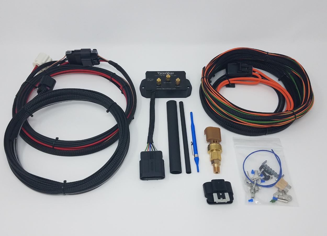 Photo 1. This kit includes all of the components necessary to drive the fuel module electrically. The minimum power rating for the PWM controller is 65A, more than 3x that of some other systems. Higher power systems are available from VaporWorx.
(Click the image to zoom in)
The basics for connecting the VaporWorx PWM are performed as follows:
- Connect battery power to the PWM controller (+ and – in)
- Connect output power to the fuel pump using the pre-installed OE sealed Delphi connector (+ and – out)
- Screw the pressure sensor into a 1/8”-NPT female thread on the pressure side of the fuel system near the outlet of the fuel module.
- Plug in the pre-installed OE sealed Delphi plug into the fuel pressure sensor.
- Connect the three-wire wire bundle from the fuel pressure sensor to the to the PWM controller using the supplied six-cavity sealed Delphi connector.
- Connect the white and violet MAP sensor ground and signal output to the six cavity connector (manifold referenced only, leave disconnected for constant pressure.)
- Connect the blue wire to the ECM fuel pump turn-on circuit.
Figure 3 shows the connections outlined above.
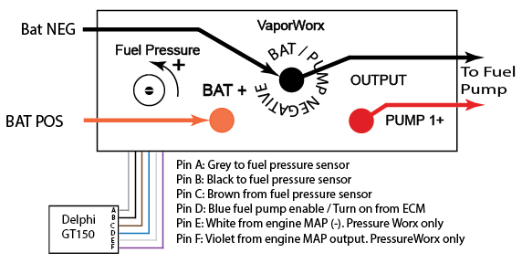
Figure 3. Basic electrical connections needed for the VaporWorx PWM controller
Another feature of PWM control is the reduction in the electrical requirement.
For example, the 5th-generation pump requires 120 watts to run at full speed at 58psi. At cruise, the PWM systems requires approximately 40 – 60 watts depending on if the system has a manifold referenced or static fuel pressure.
This reduction in power also means greater alternator life.
When does it make sense to choose a mechanical or PWM control system?
If the car is just a weekend cruiser, the engine is under 525 horsepower, and naturally aspirated, then the LS3/L99 fuel module with the adapted mechanical system will work fine.
If long pump life, long road trips, minimal pump noise, and higher horsepower are desired, then the PWM systems are the natural choice.
Advantages:
- Very low heat generation.
- Longer pump life.
- Less electrical load.
- Lower noise.
- Simple plug-and-play design.
- Single fuel line, true returnless system.
- Higher horsepower systems available (CTS-V2).
Disadvantages:
- Higher cost than a traditional aftermarket pump-on-stick design.
- Additional wiring and plumbing.
Continued Reading
This article is part 8 of the 10-part informational series: Fuel Delivery Systems – An Understanding
To continue reading in the series, use the navigation below:
Or, click here to view the full navigation/table of contents for this series.
Want to know more?
Whether you have a question about the material on this page, want to know more about our products - from purchase to installation to maintenance - or anything else, contact us anytime: we're ready to talk about your ride!