All modern EFI systems use electric fuel pumps.
Even Direct Injection engines need a “low pressure” lift pump to feed the high pressure engine mechanical pump.
These low pressure lift pumps and control systems are for practical purposes identical to the pumping systems used in port injection (LS1, Ls2, LS3, Coyote, modern Hemi, etc.) engines.
Electric fuel pumps have proven to be safe and reliable.
Many OEM’s offer 100,000 mile warranties that include the fuel systems on today’s cars. If it’s good enough for that type of warranty, then they must be very reliable if they are properly fed.
The two most popular types of electric fuel pumps are the in-tank and in-line types.
The in-tank pumps used by many aftermarket tank manufacturers are typically used in a pump-on-a-stick arrangement like that in Photo 1.
The pump is held to the stick, the fuel line outlet, by a short piece of hose and some clamps. Often the bottom of the pump is also supported with a method to secure it to the return line.
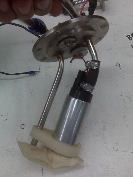
Photo 1. A typical 255lph pump mounted to a stick of stainless steel. The line on the left is for the fuel pressure regulator return.
An EFI high pressure in-line pump is just as the description implies:
Install the pump in-line external to the fuel tank. In this arrangement the fuel should be gravity fed to the pump inlet. Electric vane and turbine pumps are not good at suction, and when asked to lift fuel out of the top of the tank, it may lead to poor pump performance. An example of an in-line pump can be found in Photo 2.
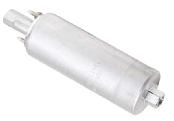
Photo 2. External in-line fuel pump.
For both the in-tank and in-line arrangements the pump or pickup can be placed in a sump.
A sump is a section that has been lowered relative to the normal bottom level of the tank. The sump is usually added to try and provide a method to control fuel slosh under less than full fuel load conditions. A basic illustration is shown in Diagram 1.
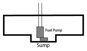
Diagram 1. A simple fuel sump design with an in-tank pump. For external in-line pumps the fuel pressure and return lines may also be attached to the sump.
For an electric fuel pump to have long life it must have a constant supply of fuel. Fuel is the life blood of the pump.
The fuel acts as a lubricant and as a means of removing heat. If the fuel sloshes away from the pump then its source of lubrication and coolant goes away as well.
Once the liquid fuel lubrication and coolant sloshes away, increased friction and heat occur in the pump.
With increased friction and heat comes accelerated wear. If the pump is subjected to this condition, premature pump failure will occur.
Once this damage condition occurs it is only a matter of time before the pump fails. It may be months later depending on how much the car is driven, and one may have forgotten the initial failure mode.
Sump advantages:
- Low cost.
- Offers better fuel control than just a flat-bottom surface.
- Can be made into a variety of shapes.
- Can have the fuel outlet and return in a non-traditional location.
Sump disadvantages:
- The fuel pump is not completely immersed in fuel / low pump inlet head pressure at low liquid levels.
- Fuel slosh can still occur under braking and cornering when fuel levels are low.
- For some it may not be aesthetically pleasing.
- Ground clearance may be a problem.
- Exposed fuel lines may be subject to road damage.
An external surge tank is another method to help reduce the effects of fuel slosh.
Surge tank designs use one electric pump in the main tank to feed a smaller second tank.
The smaller second tank also has an electric pump(s) which feeds the engine, and due to its small size and narrow shape, the effects of fuel slosh are low.
There is a return line from the surge tank to the main tank, and a return line from the pressure regulator to the main tank. A surge tank system can be found in Diagram 2.
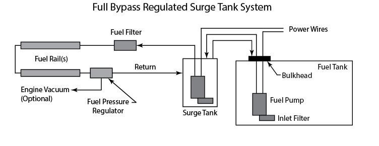
Diagram 2. Typical surge tank design utilizing two fuel pumps.
Surge tank advantages:
- Main fuel tank slosh effects minimized.
Surge tank disadvantages:
- Two pumps.
- The pump in the main tank is subject to damage under low-fuel conditions.
- Double the amount of plumbing, fittings, wiring, and power requirements.
- Difficult to fit the surge tank in many chassis designs.
None of the above systems are “returnless.”
All mechanically regulated systems have some type of fuel return.
For a true returnless system, an electronic pressure-sensitive feedback system combined with Pulse Width Modulation (PWM) must be used.
The primary thing to remember about an electric fuel pump is that its life – and the proper function of the engine – is dependent upon getting a reliable source of fuel at all times, and minimizing how hard to run it.
Types of fuel pumps:
For most all automotive use, electric fuel pumps fall into two categories: vane and turbine.
In general, vane pumps will not work well with PWM controllers in a returnless system.
Turbine style pumps can often be used in PWM control systems, but validation testing should be done.
VaporWorx has tested and confirmed that the following pumps can be controlled using the VaporWorx PWM controller with a small amount of fuel bypassed for smooth pump operation:
- Aeromotive Stealth 340 (single, dual, and triple)
- DW300 (single, dual, and triple)
- AEM320 (single, dual, and triple)
- TI Automotive (Walbro) 450lph ‘267 (single, dual, and triple)
- TI Automotive (Walbro) 525lph ‘285 (single, dual, and triple)
- TI Automotive (Walbro) 535ph ‘295 (single, dual, and triple)
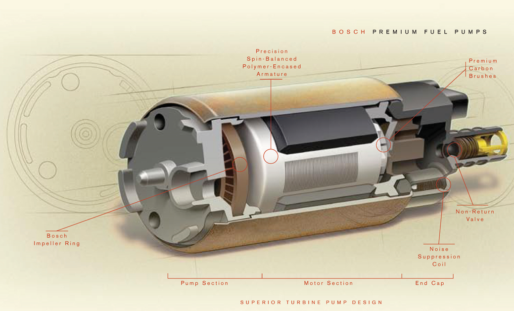
Photo 3 shows a modern turbine style pump. Note how the fuel flows around the motor section of the pump to provide both lubrication and cooling especially for the commutator brushes:
Photo 3. Turbine style pump and interior components.
(Click the image to zoom in)
For PWM to work in a returnless system, a small amount of fuel must be bypassed at all times in order to avoid a condition where the pump “chugs.”
In the OE applications, this fuel is used to drive the jet pumps.
In the case of the above pumps a small bypass hole that allows some fuel to move at all times is needed. Usually a 0.020-0.041” restrictor will work (please consult VaporWorx on your application).
On aftermarket hat/hangar assemblies that have a jet pump, such as the twin TI 450lph hat/hangers for the Pontiac G8 and CTS-V2, this bypass may be sufficient. Not all pumps are created equally. During testing some 450lph pumps PWM controlled better than others. For the 450lph pumps, having a bypass of 0.041″ diameter has shown to cover all known instances.
How big is too big for the fuel pump?
A car that has a 500hp engine will not make any more power if a fuel pump capable of supplying 1500hp is used.
An excessively large fuel will create excessive heat, and that heat ends up being soaked up by the fuel in the tank.
The best thing to do is try and match the fuel pump to the requirements of the engine, and then add 10-20% extra for safety.
Continued Reading
This article is part 3 of the 10-part informational series: Fuel Delivery Systems – An Understanding
To continue reading in the series, use the navigation below:
Or, click here to view the full navigation/table of contents for this series.
Want to know more?
Whether you have a question about the material on this page, want to know more about our products - from purchase to installation to maintenance - or anything else, contact us anytime: we're ready to talk about your ride!

